Displacement Maps
by Kenneth Styrberg
Relevant to Blender v2.35
Displacement mapping is a powerful technique that allows a texture input, either procedural or image, to manipulate the position of rendered faces. The displacement is controlled like a NOR map, a brighter texture will have a higher displacement. Unlike Normal or Bump mapping, where the normals are skewed to give an illusion of a bump, this creates real bumps. They cast shadows, occlude other objects, and do everything real geometry can do.
Displacement mapping is set up to behave as a texture channel, with one very important difference, in order to manipulate the positions of renderfaces smoothly, the faces have to be very small and this eats memory and CPU time.
For distant/non-critical items, NOR mapping should still be used. NOR maps, compared to Displacement maps, imposes very little additional CPU cost per renderface, and you can NOR map independantly of renderface count. Use of Displacement maps quickly leads to million face scenes.
Here we see the difference using NOR maps versus Displacement Maps, Figure 30. The left object has 240 faces and the right has 60717 faces at rendertime!
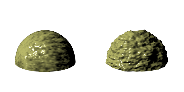
 | Use Displacement Maps when you need your geometry to be more accurate. |
Displacement Maps on Objects
Here is a list, from best to worst, that shows how different object types work with Displacement Maps.
Subsurf Meshes (Catmull-Clark) size is controlled with the render subsurf level. Displacement will work great!
Simple Subsurf Meshes Control renderfaces with render subsurf level. Displacement will work but there is a pitfall at sharp edges if the texture there is not neutral gray.
Manually subdivided meshes Control renderfaces with number of subdivides. This can slow editing down because you can not turn down the subdivide level when editing dense meshes.
Metaballs Control renderfaces with render wiresize. A small wiresize gives more faces.
The use of Displacement Maps on the following object types are possible but that they can give normal errors and visible seams when rendered.
The face count is directly connected to the U/V resolution of the surfaces. Higher resolution gives more renderfaces.
Open Nurbs surfaces
Closed Nurbs surfaces
Curves and Text
| It is recommended that you convert curve and surface object types to meshes before applying displacement. |
Interface
The interface to Displacement Maps is two buttons and two value sliders in Materials context (F5), Map To panel. Figure 31
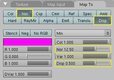
The intensity displacement is controlled with the Disp slider and the normal displacement is controlled by the Nor slider.
Displacement Map usage
There are two modes in which displacement works in:
Displace rendered vertices by intensity, vertices move along vertex normals.
Displace rendered vertices by texture normal, vertices move according to texture's NOR input.
The two modes are not exclusive. The amount of each type can be mixed using the sliders in the Materials context (F5), Map To panel, Figure 31 in the Section called Interface.
Not all textures provide both types of input though. Stucci, for example, only provides Normal, while Magic only provides Intensity. Cloud, Wood and Marble provide both Normal and Intensity. Image provides both Intensity and a derived Normal.
| Texture OSA is not currently working correct for images mapped to displacement. |
Intensity displacement, gives a smoother, more continous surface, since the vertices are displaced only outward. Normal displace, gives a more aggregated surface, since the vertices are displaced in multiple directions.
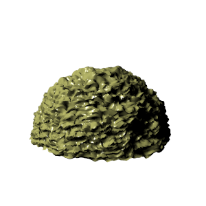
Here is an example of Figure 30 in the Section called Displacement Maps, (right object), but with a Nor slider setting of about 2.0. Note that the Nor button is still unselected! You can clearly see the more aggregated displacement when Nor settings is used together with Disp.
The depth of the displacement is scaled with an object's scale, but not with the relative size of the data. This means if you double the size of an object in Object mode, the depth of the displacement is also doubled, so the relative displacement appears the same.
If you scale in Editmode, the displacement depth is not changed, and thus the relative depth appears smaller or bigger.
The textures intensity defines the displacement. Neutral gray, RGB = 128,128,128, means no displacement. For positive displacement, Figure 33, white is a peak, black is a groove.

For negative displacement, Figure 34, it is reversed.

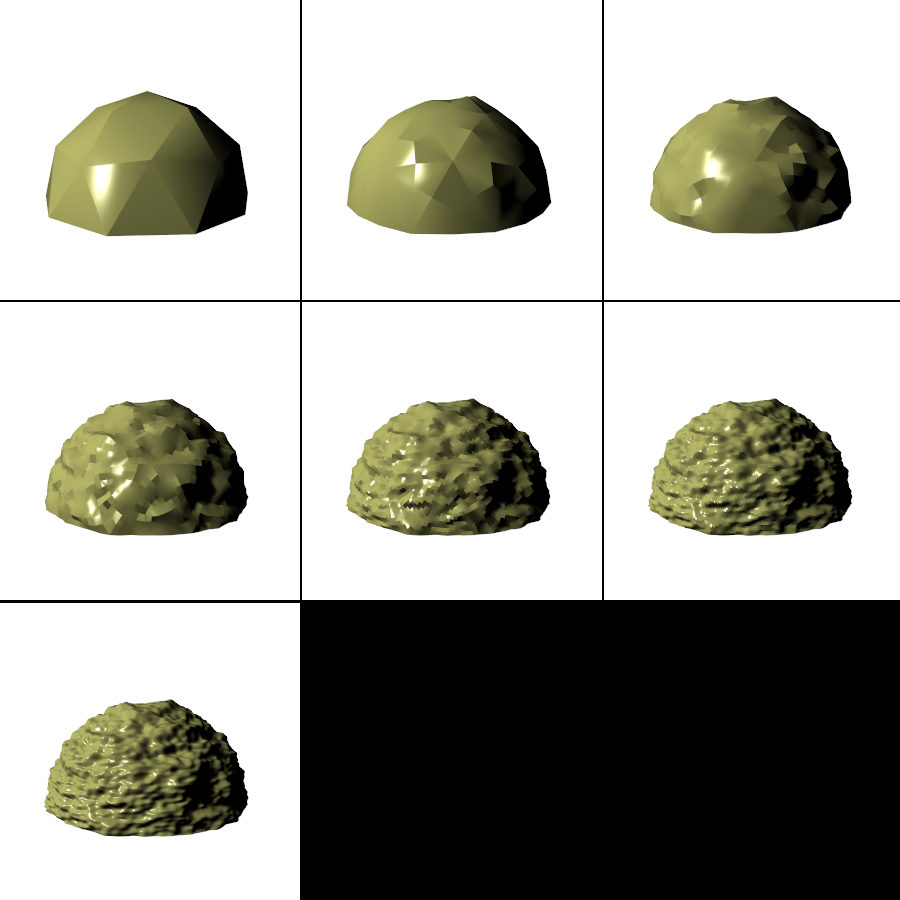
Example
Here is a example showing the effect the subdivision level has to the end result of diplacement maps. This is a Catmull-Clark subdivision type and the texture is a simple Cloud texture added to a Ico Sphere. See the Section called Catmull-Clark Subdivision Surfaces (-) in the chapter called Advanced Mesh Modelling for more on subdivision surfaces.
The subdivision levels range from 0 - (none) to 6 - (maximum) subdivision.