UV Editor and FaceSelect
Relevant to Blender 2.33
Introduction
UV mapping is a way to map 2D image textures to 3D models. It can be used to apply textures to arbitrary and complex shapes, like human heads or animals. Often these textures are painted images, created in applications like The Gimp, Photoshop, or your favorite painting application.
Procedurals as seen in the previous chapters are a nice way to texture a model. What is really nice about them is that they will always "fit". 2D images will not always fit on 3D shapes. Creating procedural textures is relatively easy, and they provide a quick way to get good results.
However, there are cases when this kind of textures is not good enough. For instance, the skin on a human head will never look quite right when procedurally generated. Wrinkles on a human head, or scratches on car do not occur in random places, but depend on the shape of the model and its usage. Manually painted images give the artist full control over the final result. Instead of playing with some numerical sliders, artists will be able to control every pixel on the surface. This means more work, but will lead to better images in the end.
A UV map is a way to assign a part of an image to a polygon in the model. Each polygon's vertex gets assigned to 2D coordinates that define which part of the image gets mapped. These 2D coordinates are called UVs (compare this to the XYZ coordinates in 3D). The operation of generating these UV maps is also called "unwrap", since it is as if the mesh were unfolded onto a 2D plane.
 | UV mapping is also essential in the Blender game engine, or any other game. It is the de facto standard for applying textures to models; almost any model you find in a game is UV mapped. |
The UV Editor
UV Mapping is done in Blender within the UV Editor window and a special mode in the 3D Window called the Face Select Mode. The UV-Editor allows you to map textures directly onto the faces of meshes.
Each face can have individual texture coordinates and an individual image assigned to it, and can be combined with vertex colors to make the texture brighter or darker or to give it a color.
By using the UV-Editor each face of the Mesh is assigned two extra features:
four UV coordinates These coordinates define the way an image or a texture is mapped onto the face. These are 2D coordinates, which is why they're called UV, to distinguish them from XYZ coordinates. These coordinates can be used for rendering or for realtime OpenGL display.
a link to an Image Every face in Blender can have a link to a different image. The UV coordinates define how this image is mapped onto the face. This image then can be rendered or displayed in realtime.
A 3D window has to be in "Face Select" mode to be able to assign Images or change UV coordinates of the active Mesh Object.
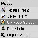
First add a Mesh Object to your Scene, then enter the FaceSelect choosing the UV face select entry in the Mode menu.
Your Mesh will now be drawn Z-buffered. If you enter the Textured draw mode (ALT-Z, also called "potato mode") you will see your Mesh drawn in white, which indicates that there is currently no Image assigned to these faces. You can control the way the faces are drawn using the Draw Edges and Draw Faces buttons in the UV Calculation Panel. If Draw Edges is activated all faces will be drawn outlined. With Draw Faces activated, all selected faces will be shown in a light pink tone (or the theme colour).
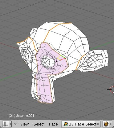
Press AKEY and all faces of the Mesh will be selected and highlighted by dotted lines. You can select faces with RMB, or BorderSelect (BKEY) in the 3D window. If you have problems with selecting the desired faces, you can also enter EditMode and select the vertices you want. After leaving EditMode the faces defined by the selected vertices should be selected as well.
Only one face is active. Or in other words: the Image Window only displays the image of the active face. As usual within Blender, only the last selected face is active and selection is done with RMB.
Change one window into the UV Editor/Image Window with SHIFT-F10. Here you can load or browse an image with the Load button. Images have to be multiples of 64 pixels (64x64, 128x64 etc.) to be able to be drawn in realtime (note: most 3D cards don't support images larger than 256x256 pixels). However, Blender can render all assigned images regardless of size when creating stills or animations.
Loading or browsing an image in FaceSelect automatically assigns the image to the selected faces. You can immediately see this in the 3D window (when in Textured view mode).
Unwrapping tools
In the 3D window, you can press UKEY in FaceSelect mode to get a menu to calculate UV coordinates for the selected faces. You can also perform an unwrapping using the UV Calculation Panel in Edit Buttons. This panel also provides better control over the unwrapping process.
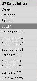
The available UV unwrapping algorithms are:
Cube This determines cubical mapping.
Cylinder, Sphere Cylindrical/spherical mapping, calculated from the center of the selected faces.
Bounds to 1/8, 1/4, 1/2, 1/1 UV Coordinates are calculated using the projection as displayed in the 3D window, then scaled to the given fraction of the image texture.
Standard 1/8, 1/4, 1/2, 1/1 Each face gets a set of default square UV coordinates which are then scaled to the requested fraction of the image texture.
From Window UV coordinates are calculated using the projection as displayed in the 3D window.
LSCM UV coordinates are calculated using the Least Squares Conforming Maps algorithm. Use it together with the marked seams.
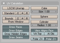
In the UV mapping panel, you can tweak the way the mapping is done and how it is shown in the 3D window when the model is in Face Select Mode.
With View Aligns Face enabled, Cylindrical and Spherical unwrapping is affected by the view. The view is supposed to be in front of the Cylinder/Sphere, with the caps at the top and bottom of the view. The Cylinder/Sphere is cut at the opposite side of the view.
Size and Radius define the scaling of the map when using Cube or Spherical/Cylindrical mapping respectively.
With VA Top (View Aligns Top) enabled, the view must look through the Cylinder / Sphere. It is cut at the top of the view. With this activated you can also define how the view is rotated in respect to the poles using Polar ZX and Polar ZY options.
If Al Obj is enabled, the Cylinder/Sphere is rotated based on the Object's rotation.
Draw Edges and Draw Faces in the panel activate visualization of edges and faces in the 3D Window while in Face Select Mode. Selected faces in this mode will be drawn in a transparent purple (or the theme color), similar to Edit Mode. Drawing of Seams in Edit Mode and Face Select Mode can be toggled with Draw Seams. The colors of seams can also be changed in the Themes options.
Editing UV coordinates
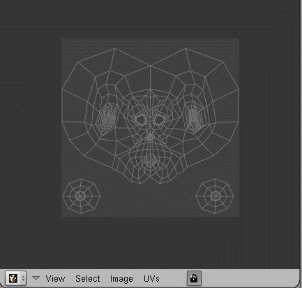
In the UV Editor you will see a representation of your selected faces as yellow or purple vertices connected with dotted lines. You can use the same techniques here as in the Mesh EditMode to select, move, rotate, scale, and so on. With the Lock button pressed you will also see realtime feedback in 3D of what you are doing. Scaling and Translating of vertices can be done in the local X or Y axis of the map if needed. Just press XKEY or YKEY after entering the scale command (SKEY). Proportional editing tool is also available and it works the same way that in Edit Mode for meshes. Vertices in the UV Editor can be hidden or shown using the HKEY and ALT-H respectively, the same way as in Edit Mode.
There are several selection modes available in the UV Editor. Since a vertex is drawn in the Editor for each face it belongs, sometimes is hard to tell if we are selecting the same vertex or not.
With Stick UVs to Mesh Vertex enabled, a RMB click will not only select one UV vertex, but also all the UV vertices that belong to the same mesh vertex. You can use this mode even if it is not activated in the menu, by keeping CTRL pressed when selecting a vertex.
Stick Local UVs to Mesh Vertex works in the same way, but only select the UVs that are 'connected', meaning they are within a 5 pixel range of the first selected UV. You can also use this mode even if it is not set as default, by keeping SHIFT pressed when selecting a vertex.
These options are toggled on/off by respectively pressing CTRL-C and SHIFT-C.
With Active Face Select enabled, a RMB click will select a face, and make it the active face. This can be toggled on/off by pressing CKEY.
For all three of these options a special icon is displayed in the bottom left of the UV Editor. Note that Active Face Select and Stick UVs to Mesh Vertex can also be combined.
Unlink Selection will based on the current selection, only leave those UVs selected, of which the faces are fully selected. As the name implies, this is particularly useful to unlink faces and move them elsewhere. The hotkey is ALT-L.
Select Linked UVs works similar to Select Linked in the 3D View. It will select all UVs that are 'connected' to currently selected UVs. The difference with the 3D view is that in the UV Editor, UVs are connected 'implicitly'. Two UVs are considered selected if the distance between them is no longer than 5 pixels. The hotkey is LKEY.
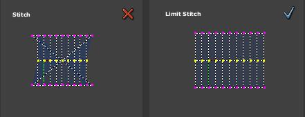
Different parts of a UV map can be stitched if the border UV vertices correspond to the same mesh vertices by using the Stitch command (VKEY). The Stitch command works joining irregular outlines, just select the vertices at the border line using the "Stick UVs to Mesh Vertex".
Limit Stitch works in the same way. The difference is that it only snaps together UVs within a given range. The default limit is 20 pixels. Its advantage over 'Stitch' is that it prevents UVs, that are supposed to stay separate, from being stitched together. You can see on the screenshots how Limit Stitch prevents wraparounds when stitching together two parts of a Cylinder.
You can merge UVs that do not correspond to the same mesh vertex by using the Weld command (WKEY). You can also use the Weld command to align in X or Y several vertices. After pressing WKEY press XKEY or YKEY to choose which axis you to align to
Some tips:
Press RKEY in the 3D window to get a menu that allows rotation of the UV coordinates.
Sometimes it is necessary to move image files to a new location on your hard disk. Press NKEY in the ImageWindow to get a Replace Image name menu. You can fill in the old directory name, and the new one. Pressing OK changes the paths of all images used in Blender using the old directory. (Note: use as new directory the code "//" to indicate the directory where the Blender file is).
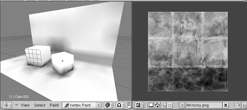
You can also use FaceSelect and VertexPaint (VKEY) simultaneously. Vertex painting then only works on the selected faces. This feature is especially useful to paint faces as if they don't share vertices. Note that the vertex colors are used to modulate the brightness or color of the applied image texture.
LSCM Unwrap
LSCM means Least Squares Conforming Map. This is an advanced mathematical method to automatically create a UV-mapping while keeping texture stretch and deformation to a minimum. It works by preserving local angles. Just as any other existing UV unwrapping mode, it will unwrap the selected faces in UV Face Select Mode. It is available by either pressing the UKEY key, and then choosing LSCM, or by choosing LSCM Unwrap from the UV Calculation panel.
To be able to correctly unwrap a mesh with LSCM, you must make sure your mesh can be flattened without too much deformations (in mathematical term, it should be equivalent to a disc). This is done by defining seams, i.e. places where the mesh will be cut. You don't need to add seam if the mesh can be unwrapped directly in a plane.
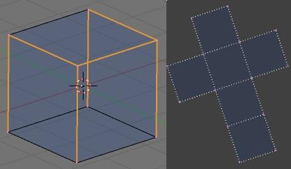
In Edit Mode, selected edges can be marked or cleared as seams, using CTRL-E. Here you can see a cube with seams, and the resulting UV map after applying LSCM.
Often a mesh cannot be unwrapped as only one group of faces, but must be cut up into multiple groups. If seams divide the selected faces into multiple face groups, then LSCM unwrapping will unwrap them separately, and position them in the UV Editor so the face groups don't overlap. To ease selection of face groups, Select Linked in UV Face Select Mode (press LKEY) will select all linked faces, if no seam divides them. This way, you can select a face group by selecting one face of the group, and executing Select Linked.
To further tweak the result, UVs in the UV Editor can be pinned to a fixed position. If LSCM is executed, these UVs will stay in place, and the resulting UV map will adapt to the pinned UVs. In the UV Editor, selected UVs will be pinned or unpinned by pressing PKEY or ALT-P. Pressing EKEY in the UV Editor will launch LSCM unwrapping on the faces visible in the UV Editor. Pinned UVs are marked in red.
Texture Paint
Once you have loaded an image into the UV Editor, you can modify it using the Texture Paint mode. Use the Paint Tool option in the View menu, to modify paintbrush Size, Opacity, and Colour. Currently there is only a default brush to paint, but work is being done to provide more brushes.
All changes you make will be instantly reflected in the 3D View if the model is in potato mode. However the modified texture will not be saved until you explicitly do so. Use the Save Image option in the Image menu to save your work with a different name or overwriting the original image.
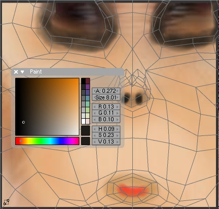
Notice that the Draw Shadow Mesh option becomes very helpful to keep a reference of the UV map while texture painting.
Rendering and UV coordinates
Even without an Image assigned to faces, you can render textures utilizing the UV coordinates. For this, use the green UV button in the MaterialButtons (F5) menu.
If you want to render the assigned Image texture as well, you will have to press the TexFace button in the MaterialButtons. Combine this with the VertexCol option to use vertex colors as well.